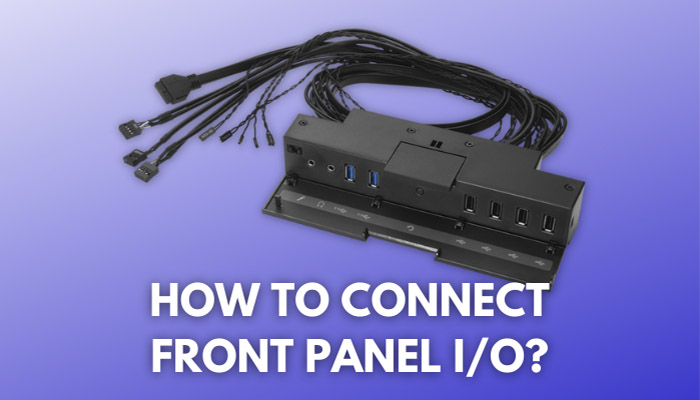
Plugging in your front panel I/O connections can be a bit confusing while building a PC. Most motherboards come with no legend on the board, leaving users in further trouble.
However, almost all motherboard manufacturers have standardized the pin layout, thereby making connecting these pins much easier than they used to be. Following this standardization, a few case manufacturers also have shifted to one connector for all of the headers. This makes connecting these headers a breeze, but only a handful of case manufacturers have done this to date, and the majority of options in the market still rely on separate pins for each header.
How do you connect Power SW, Reset SW, HDD LED and power led to the motherboard?
Most motherboard manufacturers have shifted to a standard header layout. The front panel headers have been shifted to the right bottom of a board, and, generally, the headers are placed as follows:
- The first two headers from the left top are Power LED headers. The one on the right is the negative header, and the one on the left is the positive header. The Power LED headers do not have any polarity, so you can plug them in any way, and the system will be fine.
- The third and fourth headers from the left top are the Power SW connection.
- The third and fourth headers from the left bottom are the Reset SW connection. It is right below the Power SW connection.
- The first and second header from the left bottom is the HDD LED connection. Like the Power LED connection, they have no polarity. But, you can plug the negative connection to the right and the positive connection to the left following the convention.
These connections are common to all front panel connectors. After this, the fifth header from the top left has no pin, and the fifth connection from the bottom left is a +5V DC connection.
Some headers have a few extra connections after this. These include a motherboard debug speaker connection in the 6th to the 9th connection from the top left. Headers with extra connections also include an extra Power LED connection. The positive header is the 6th pin from the bottom left, and the negative Power LED header is the 8th pin from the bottom left.
The seventh, ninth and tenth connections from the bottom left, and the tenth connection from the top left have no headers.
Two figures with the header layout are shown below:
We hope this guide helped you to connect all of your front panel connectors. In case of any doubt, leave a comment below and get the discussion started!


